"Flickering" is a common issue that comes up for anyone who uses
Final Gather in Mental Ray to compute indirect illumination for a scene containing moving objects. This tutorial addresses the flickering problem for animations with dynamic movement; that is, characters, creatures, etc, not just a moving camera. I assume you have some experience with Final Gather, but I will explain some of the most pertinent attributes needed to better understand the workflow presented here. The technique used in this tutorial is applicable to Maya 2008 and newer versions as it relies on the
mental images production shader library "mip_render_subset" node. The video below shows the resultant test scene featuring flicker-free Final Gather indirect illumination:
Even in the simple scene above, Final Gather will cause flickering, due to the inherent nature of its random sampling methods. Keep in mind that a frozen Final Gather (referred to as FG henceforth) map works well even on objects that move slightly (such as leaves in the breeze). In the video below, a Paint Effects plant, converted to polygons for rendering in Mental Ray, is flickerless despite its slight motion; this demonstrates that a frozen FG map with very low settings works not just for static objects:
So it's important to know that a frozen FG map is quite flexible, but it has limits, particularly for objects that encounter major lighting changes during an animation such as a character.
Note: Once the mip_fgshooter is implemented into Maya with an intuitive interface, the particular workflow presented in this post won't be necessary anymore, for most situations. For now, there's a few scripts that allow you to try out the mip_fgshooter, such as this one here: fgshooter UI for Maya. There is a discussion of this over at CGTalk forums. Check it out here: Flicker-free Final Gather.
After some experimentation I've settled on a relatively good workflow for achieving a flicker-free FG result; here's the outline listed below.
- Hide moving objects, compute a Final Gather Map for objects that don't move.
- Freeze the FG map, then unhide all moving objects, render the scene normally.
- On a new render layer, set FG as a layer override to "Rebuild", with a new FG map override.
- The new map will be for moving objects, be of high quality, and will be rebuilt (never frozen).
- Attach the mip_render_subset node as a lens shader to speed up rendering of second pass.
- Output the "indirect_result" of the mia_material_x to a surface shader, assign the surface shader to the mia_material's geometry, and associate with mip_render_subset.
- Render the scene, mip_render_subset will only render selected objects and/or materials; essentially creating a fast indirect pass for moving objects.
- You'll now have a FG-only pass for your moving objects, to be added onto your original render in the composite.
This method will force you to render the scene twice, but only at the cost of computing an additional FG pass along with ONLY the indirect contribution of the moving objects (characters, vehicles, etc), which shouldn't add much to your render time. The reason the scene requires rendering twice is because FG won't allow setting of Rebuild and Freeze for different individual maps in the same rendering session. Since FG is view-dependent, resolution-dependent, and dependent on how much geometric details and lighting contrast the scene contains, the settings you converge on for one scene will probably not work for other scenes, so the more you know the better you'll be able to get a good result fast. Below are the settings for the above blocks/bricks collision test video for the "Frozen" portion of the FG pass. I'll describe some of the relevant settings, but if you don't know all of the settings in FG and are serious about using it, I recommend you taking some time and make a practice scene, check out the manual, online videos, and experiment with the settings; you'll be glad you did.
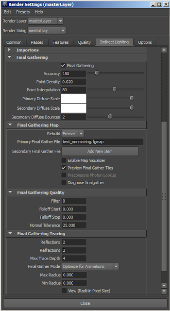 |
| Very low but adequate frozen FG settings for this simple scene. |
Something to note with Frozen FG maps: you're able to get away with really low FG settings, particularly the
Point Density defining just how many FG points will be sampled from the camera view, while using
Point Interpolation to smooth the map out by averaging neighboring FG points, along with the
Normal Tolerance which is a threshold that allows interpolation of nearby points to occur only after a certain angle between their respective surface normals is met. As a note on just how resolution dependent FG is, for example, if you set your resolution from 1280x720 to 1920x1080, you're essentially quadrupling the amount of Point Density without even changing the attribute.
Accuracy defines the amount of rays casted from each FG point, which increases render time while better estimating the indirect illumination of each FG point. Accuracy is usually worth increasing over Point Density, but it will only go so far, as Point Density is arguably the most important setting. If you're working in a tone-mapped workflow with photometric lights (or the Sun and Sky system), you shouldn't have to change the
Diffuse Scales (which are gains on the FG results, allowing surfaces to reflect more or less indirect light than they are supposed to for plausibly accurate light transport in the render).
Secondary Diffuse Bounces isn't really relevant here, but if you don't know, it adds more bounces of FG points. By default there is 1 primary indirect bounce of light (there has to be, or else no indirect light would exist), and the secondary bounces are set to 0 by default. Adding a few more indirect bounces will yield a more accurate result with usually little addition to render-time, so long as the FG settings aren't too high. The setting
Optimize for Animations (called Multiframe mode in the Mental Ray manual) will usually help on scenes with animation, as the
Max Radius parameter is used to limit how far in world units FG interpolation can occur, but it's not always better than the
Automatic mode, even for animations. While setting the FG
Filter to higher values (such as 2) reduces flicker, it also produces a more biased result (meaning not as accurate). FG is as unbiased as possible with the Filter set to 0, the default, and I recommend you keep it there. On the concept of unbiased indirect lighting, an interesting mode to try out is
No FG Caching. This is a brute force method, therefore it's highly accurate but computationally expensive, though it will cause no flickering (only sub-pixel noise). In the brute force method, Accuracy defines how many samples will be taken; the more samples, the less noisy the image, the longer the render time.
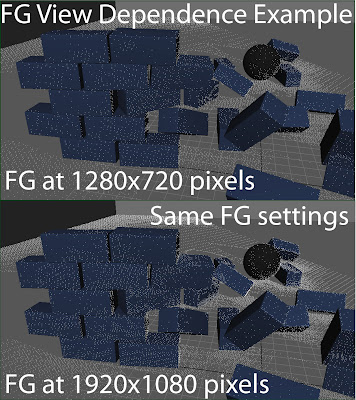 |
| Same Point Density, number of points increase at higher resolution. |
Speaking of physically-plausible renderings, when using the Mental Ray Sun and Sky, setting the RGB Unit Conversion of the mia_physicalsky to 0.318 for each RGB component (1/pi or 1/3.1415927) converts the raw values of the Sun and Sky so that they fit easily into the mia_exposure_photographic tone mapper, meaning the Cm2 factor (the Candela per meter squared conversion factor) doesn't have to be adjusted. The
Mental Ray architectural design manual describes how 1/pi is derived: "The value 0.318 (1/pi) originates from the illuminance/luminance ratio of a theoretically perfect Lambertian reflector". This is useful to know if you're using mia_exposure_photographic and are trying to replicate a real-world camera setup without having to change the Cm2_factor to some arbitrary number. In addition, each pixel in the final floating-point rendered image will be represented as candela per square meter luminance values.
Alright, so the main idea here is to create a Frozen FG pass ONLY for the objects that aren't moving OR are moving very little (think of leaves moving in a gentle wind). This will entail simply hiding those objects you know are going to flicker with low FG settings, then unhiding them after the FG map has been computed and Rebuild set to Freeze. Always remember to disable the option
Enable Default Light in the Common tab of the Render Settings window, as the default light will, among other things, cause a lighting change if you're batch rendering, cancel and then continue the render using batch scripts, so this setting needs to be off. Feel free to use the Render Passes and such; this will be a beauty render without indirect lighting on the moving objects; we'll take care of the FG on those objects next. Just in case you don't know how to create a Frozen FG map, here's a quick explanation, but this isn't the point of the tutorial so I'll make it quick:
To create a Frozen FG map, define a map first in the Final Gather File field (an extension name doesn't matter, though I use .fgmap), then enable the
Preview Animation mode in the Preview section of the Options tab of the Render Settings. Preview Animation will render out your scene but won't save files in this case. You'll ONLY be calculating the FG map for your main rendering camera. To set the renderer to render only the FG pass, under the Features tab, set the Render Mode to
Final Gathering Only. Image sampling (anti-aliasing and such) settings don't matter and will have no effect, since FG is being rendered only. Then under the Common tab, set the
By frame attribute to a setting such as 10, or 5, there usually isn't a need to render every frame for the FG map, unless the camera view is covering a massive change per frame. Keep in mind that the pixel resolution of the image does matter, so you'll need to set that to your target output pixel resolution, also under the Common tab. Now render the current frame and Mental Ray will calculate the FG data for the length of the animation. Remember to switch Rebuild to Freeze and unhide any objects (such as your characters/creatures) you didn't want in the frozen FG solution when you're ready to render again. Here's a quick explanation on the Rebuild modes in Final Gather:
Rebuild On: Overwrites the FG map on every render, and with each frame advance at render-time.
Rebuild Off: Appends (adds) FG points to the map, as needed, without overwriting it.
Rebuild Freeze: Reads from the FG map, doesn't overwrite nor append anything to it.
Alright, now you have a beauty render with frozen FG on all static (along with slightly moving) objects. Those highly moving objects have no FG contribution, so now it's time to render out the scene again, but without doubling the render time, and with minimal effort. If you don't have the mental images production shader library exposed in Maya 2011, in the MEL command line type:
createNode mip_render_subset
Or, if you'd like to expose these shaders in the Maya 2011 Hypershade without having to manually create them using the createNode command, copy the script
mentalrayCustomNodeClass.mel from the directory (in Windows) "C:\Program Files\Autodesk\Maya2011\scripts\others\" and paste it into your local user scripts directory located at "C:\Users\YourUserName\Documents\maya\2011-x64\scripts\", ensuring that if you make a mistake, you can just delete your copy and Maya will work again. Change this line near the bottom of the new file:
int $enableMIPShaders = (`optionVar -query "MIP_SHD_EXPOSE"`== 0);
After the "MIP_SHD_EXPOSE"`==, change the 0 to a 1. (This is a boolean variable, 0 equals "off" and 1 equals "on", so you're now exposing the production shader library to the Hypershade when Maya loads).
Also, verify they are loaded by going to "Window > Rendering Editors > mental ray > Shader Manager". Make sure "production.mi" is loaded.
In the picture below, the mip_render_subset node's attributes are shown.
The mip_render_subset node wants you to define at least one object (by typing in the name of a
shape node of a
geometry object) OR a material's
shading group node (not the material, the shading group, because Mental Ray's material is represented as the shading group node in Maya). By the way, if you define a material and a selection of objects, the shader only works if all conditions are met (that is, objects with the particular material (SG node) selected). So what does this node do anyway? Well, it is designed to ONLY render the defined objects AND/OR objects with the chosen material (you can also just define a material and no objects). It's a "quick-fix" shader for re-rendering an object in a scene that was rendered incorrectly (such as wrong material settings that can't be corrected with a matte in compositing), but without having to re-render the entire scene again nor having to isolate the object manually. In this tutorial, we'll use this shader to "isolate" the moving objects in the scene for the second render pass. The shader is applied as a lens shader on the renderable camera under the "mental ray" section. If you already have a lens shader applied (such as mia_exposure_photographic), then simply choose the
Create button under the
Lens Shaders section of the camera shape node attributes. Note that only the first mip_render_subset node will render, as these are unstackable. Here's a simple demo of using the mip_render_subset for isolating a specific material:
mip_render_subset - Basic Example
To enter an object into the mip_render_subset, simply copy/paste its shape node name. Press
Load Attributes in the Attribute Editor to refresh/redraw the window, allowing the next empty entry in the object array list to display. Now just add the objects you want to be isolated in the render. To keep things quick, I won't explain the other settings, as they aren't relevant in this tutorial, but, there is one setting that can speed up rendering at the expense of accuracy:
Full Screen FG. Full Screen FG is enabled by default, and it does what is reads as: computes the FG pass for the whole scene first, then renders only the objects/materials defined by this lens shader. If you disable the Full Screen FG option, the FG pass will only compute for the isolated objects, so the render time will definitely be faster, but at the expense of accuracy. It is highly recommended you keep this setting on, which is the default. We're not done with the mip_render_subset yet, I've just explained what it is and the general idea of how it's used; you'll soon see how it'll be used along with the indirect_result shader attribute to ONLY render out the FG contribution for the moving objects once I go over some of the FG settings for this second pass, as they are entirely different from the frozen FG map pass.
Before I move on, I'd like to mention that I'm using
the
Render Layers feature within Maya to assign overrides to various attributes I want to change for the selected layer only, which show up as an orange color. The overall concept is simple but there's a lot you can do; if you haven't utilized them in your workflow yet, I highly recommend you read about
Render Layers in the Maya manual. There's also plenty of video and such on the internet describing their use.
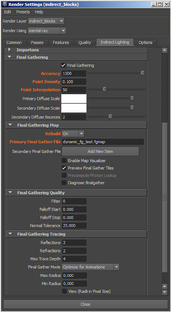
This second pass will require the settings for FG to be considerably higher. For example, each FG point is casting 1500 rays to estimate their indirect illumination. The Point Density is at 0.100 (which is barely enough for this particular scene). Point Interpolation has been set to 50, which eliminates some of the flickering almost for free, but keep in mind that for points to "get the most out of interpolation", you need a certain amount of points that are eligible for interpolation (remember the Normal Tolerance setting). This means that if you don't have enough Point Density in your animation to match the smaller details in the scene, interpolation won't be able to help much, meaning for those areas, Accuracy will have to be high enough to subdue the higher potential for flickering. What I'm saying is that Point Density is the most important setting and will determine if the animation will flicker or not; you need to have a certain amount of FG points or else you can't eliminate the flicker, but it really is a balance between a high enough Point Density along with relatively high Accuracy (for good estimation of each of those important FG points), then use the Interpolation setting for the final smoothing; 25-75 are pretty good for Point Interpolation on typical scenes. Remember that if you change the render resolution, the FG results will look different, so tweak the final settings at your target render resolution. So what settings do you use? There are no specific ones since each scene is different; with experience you'll be able to set up a scene's FG faster. Enable
the option
Diagnose Finalgather, and you'll be able to see every single FG point sampled from the camera into the scene, while the
Map Visualizer will allow you to see the points in the viewport. Consider that some of those points will be interpolated if they're close enough to each other AND if they fit within the Normal Tolerance. Generally you won't have to adjust Normal Tolerance, but there needs to be a sufficient amount of FG points to resolve a good amount of the detail in your scene; along with a relatively high Accuracy setting, which is cheaper than increasing the Point Density and will yield similar results. Remember the Rebuild mode here is On, allowing FG to compute at each frame.
Another very good tip to know about Final Gather is that as you're tweaking it, you're able to get almost instant feedback if you write out a temporary FG map and then set the Rebuild mode to Freeze; you can then adjust some settings in the IPR (Maya's interactive renderer) without having to wait for the FG to calculate again. The settings you're able to tweak with a Frozen FG map: Point Interpolation, Diffuse Scales, Filter, and the Min/Max Radius. Of course, tweaking Accuracy and Point Density require the map to be re-computed. The
Min Radius and
Max Radius are advanced settings which are best left at their defaults of 0.000, but they can be adjusted if needed. They are good for forcing Point Interpolation to only interpolate points that are near other points to a certain radius in world space; Mental Ray computes internal defaults for the Min and Max radii and you probably won't have to adjust them often, but they're available. Though these FG settings are somewhat "high" (not high at all for a single over-night frame render, but for animations, settings need to be low), they won't fill in details nor color bleeding. That's fine, you can use the mia_material_x's
Ambient Occlusion with Color Bleed option, or rendering out a traditional Ambient Occlusion pass for compositing will be fine too. An interesting way to use an AO pass is to color correct the image but set the AO pass as a mask into the color correct, controlling gain and such, but also, adding a bit of saturation back into the darker areas, again using the AO pass as a mask. This method is fine, but if you're rendering in passes (diffuse, reflection, etc), you can apply AO in a more correct way, by rendering out an ambient color or indirect lighting pass, gain down that pass using the ambient occlusion pass as a mask, then add the direct/diffuse lighting on top of the indirect pass, which eliminates the "dirty" look of most renders using ambient occlusion, due to the AO effect occurring in direct light. Now onto setting up the FG pass of the moving objects.
You've already rendered out the moving objects in the first pass; they just have no FG contribution to them; well now you're going to render the second pass, but it will only contain FG for those objects, and you'll be able to composite this new render onto the first one by simply adding color values, with the added bonus of being able to adjust the amount FG contributes to those moving objects if needed. This will be done by utilizing the indirect_result attribute of certain Mental Ray shaders optimized for pass-based rendering, such as mia_material_x and mia_material_x_passes that each expose outputs such as diffuse, opacity, etc.
Side Note: For the sub-surface scattering shader, you should incorporate its scattering result into the mia_material_x_passes'
Additional Color attribute, make sure the SSS shader's diffuse and specular contribution to 0, allowing the mia_material to handle diffuse, glossiness (specular), reflectivity, etc, while the SSS shader does what it does best, sub-surface scattering and only that; you could also mix specular/glossiness from both materials. Also remember to assign the misss_fast_lmap_maya node to the mia_material shading group's
Light Map Shader slot. If you're to be rendering linear color space
HDR (high dynamic range) images, make sure to disable
Screen Composite under
Algorithm Control of the SSS shader. This keeps the result physically plausible, by keeping the material from reflecting more light than what illuminates it (that is, it obeys the conservation of energy concept). These recommendations for using the SSS shader are from the person who actually wrote it: Zap Andersson (
Zap's mental ray tips). I've digressed somewhat, let's get back to the Final Gather stuff, but rendering with color management (aka "linear workflow") is very important.
If you're using the mia_exposure_photographic lens shader and you want to maintain linear color output for HDR images (essential in allowing compositing math to apply in a predictable and proper way), remember to set Burn Highlights to 1, Crush Blacks to 0, and Gamma to 1.0 before you do the final render. In the compositing application, you should use a color
Lookup Table (LUT) to transform the image to sRGB (appropriate for all typical LCD monitors) color space for viewing, while allowing the underlying compositing math to operate in a linear fashion.
For the shaders being used in this second pass, in order to isolate and only render the indirect element (instead of everything else too), you'll connect the
indirect_result attribute of the mia_material_x (or _passses, whichever you're using) to a new Surface Shader's
outColor attribute. The connection is displayed below in the Hypershade. As a side tip, if you didn't know, the green arrow represents a triple-attribute connection such as XYZ, dark blue represents a single connection such as integer to integer, a cyan arrow represents double attributes connected (such as UVs), and purple means a connection to a table of data. The connection we're making here is a simple color to color (3 values of RGB to another 3 values of RGB). Now assign the Surface Shader to the geometry the incoming mia_material was assigned to; if you're using
Render Layers, the material will be assigned as a
Material Override. Regardless of whether you're using Render Layers, if you render the object now, it will only produce FG or any other indirect result. This is faster and more efficient than re-rendering the object with all of it's shading qualities, those of which were already computed in the first pass.
The next step is to add the moving objects into the mip_render_subset object list. If you have a lot of objects that use the same material, then simply use that material instead of adding the objects manually. Copy/paste geometry object shape node names AND/OR a material's shading group name into their respective fields of the mip_render_subset node. Make sure the node is applied as a lens shader to the renderable camera. Now render the scene and you'll see the FG is computed for the entire scene, but once it finishes, only the objects/materials listed in the mip_render_subset render, AND only their indirect illumination renders, meaning a really fast render compared to computing texture filtering, blurry reflections, and such. If you want a faster rendering without having to disable the Full Screen FG option in the mip_render_subset node, then you might want to disable
Final Gather Cast and
Final Gather Receive on the distant objects in the scene, ones that wouldn't contribute much if any FG to the objects/materials listed in the mip_render_subset, thus skipping them entirely from the FG computation. This will decrease accuracy of the light transport a bit but will speed up the rebuild of each FG pass on each frame. Below is the result, the indirect result only of the blocks themselves, and they aren't flickering!
That's really all there is to it. Use your compositing application to composite the results onto the original first pass. This may not be the best method to do flickerfree FG in Maya, but there doesn't appear to be much information on the internet about it, and so after some experimentation I found this workflow to be the most efficient and fast, for now. If you have a high dynamic range scene with an intense amount of contrast differences, you'll probably be asking FG to do more than is practically feasible. Another way to smooth out FG is to use a blurred environment map that only FG rays see by means of using a ray switcher; the production shader library includes several such nodes, and keep in mind the usefulness of the mia_envblur node and the
Single Sample from Environment attribute in the mia_material. If all else fails, you can always render a Frozen FG map for the static objects and then
Light Link a directional
Light Rig (without shadows and specular on the lights disabled) onto the moving objects; for best results you can render out the contribution (not talking about Contribution Maps of Render Layers) of the Light Rig lighting the moving objects with all other lights disabled and everything else matted out, then combine that result in the compositing stage to fake indirect illumination; I recommend rendering a test FG image and then try to match that in the compositing program. It won't be perfect but plausible results are achievable that are guaranteed to never flicker. As proof of the Light Rig concept on the moving objects, the video below shows the moving objects lit by a light rig comprising of just around 16 or so directional lights, without shadows, along with the Sun and Sky. This isn't a bad way to go if you're working with an exceptionally complex scene that would require unavailable increases in render time for the significantly more expensive Final Gather computations on extremely detailed moving objects.
Please feel free to leave comments and suggestions!


